How to Read Your Architect’s Drawings – Part 2
In Part 1, we looked at what the main types of architectural drawings show – plans, elevations, sections and details. Now, we’re going one step deeper – because even once you know what type of drawing you’re looking at, you’re still faced with a jumble of lines, arrows, numbers and hatch patterns that might feel like a secret code.
Good news: it is a kind of secret code, and this post is here to help you crack it….or to at least dent it!
Not all lines are created equal
Architects use different line weights (aka line thicknesses) and line types (solid, dashed, dotted) and colours to tell you different things.
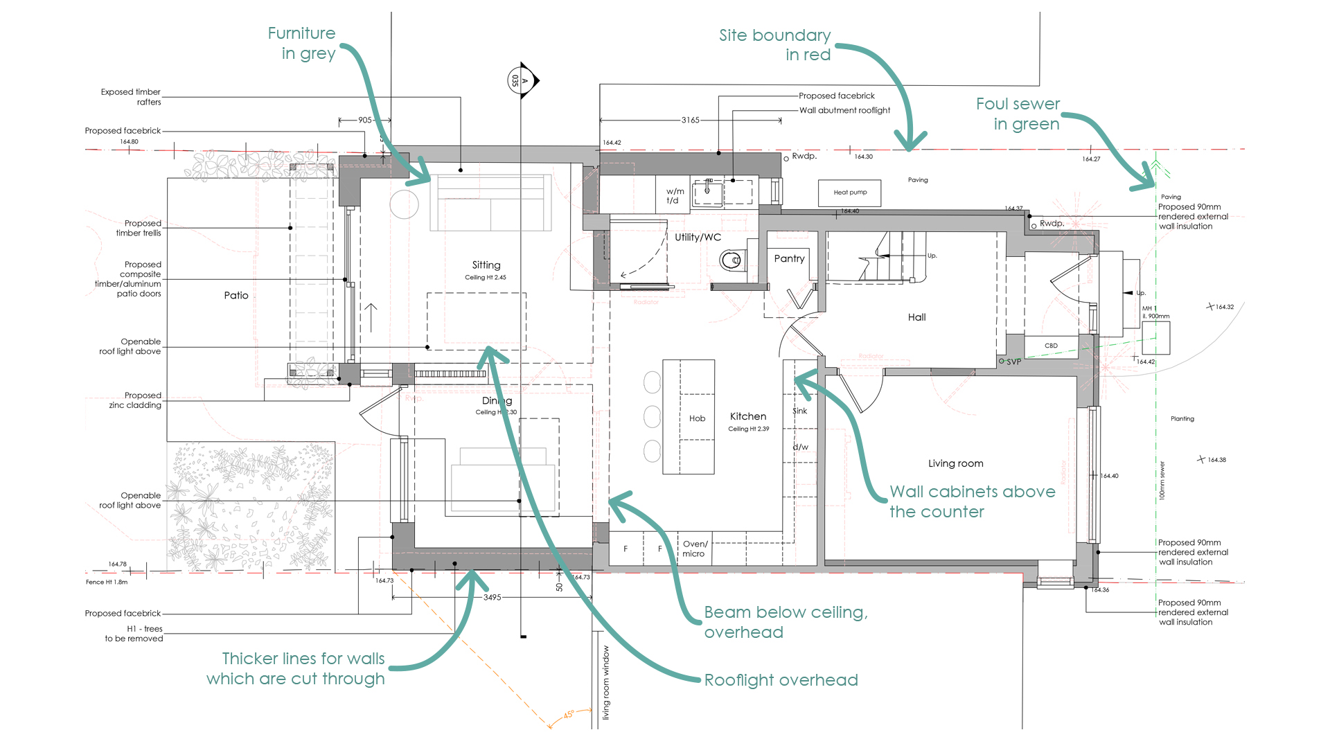
* Thicker lines = important or solid elements (like walls being cut through)
* Thinner lines = background info (like furniture, fixtures or the floor below)
* Dashed lines = something above your head, or hidden from view (like a roof overhang or a beam)
Oh, and those light pink dashed lines – they’re everything that is being demolished!
Shading with meaning
Architectural drawings often use hatching — patterns or shading — to indicate materials, construction types or areas of focus.
Our common hatching methods include:
* a solid darker grey for new structure (see the plan above)
* a solid lighter grey for existing structure (see the plan above)
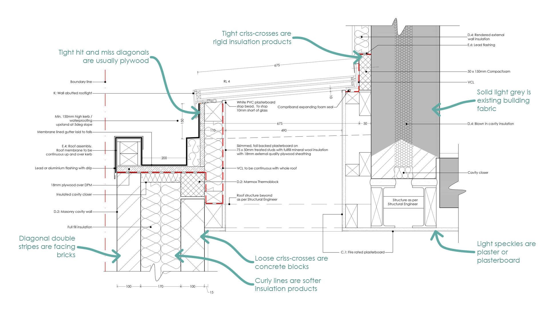
Once we move into the detailed Building Regulations drawings these solid grey hatches are switched out with different patterns to reflect materials. Below is a snippet of some of the hatches we use.
Sometimes, hatching is just used to draw attention to one part of the drawing (e.g. the new work), while other areas are left blank or faded out.
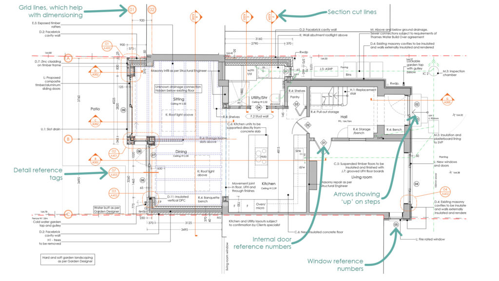
The secret symbols
Architects love a good symbol. It saves space, keeps things tidy and makes the drawing more readable…… for those of us who’re in on the secret.
Here are some common symbols that we use on our general drawings.
Numbers that matter
This is the bit that most clients jump to – and fair enough! You want to know how big the space is. We show measurements in millimetres, but can also include feet and inches (although, imperial units don’t really mean much to us, sorry!!) and our dimension lines are usually:
* Straight lines with little arrows at each end, with a
* Number in the middle to show the length of that ‘thing’
Usually there are layers of dimensions:
* An overall dimension – the length of the full wall
* Door and window opening sizes and their relations to surrounding structure
* Internal room sizes. Keep in mind that measurements to bricks and blocks exclude plaster finishes
How far things are to other things are usually included on each of these layered dimension runs.
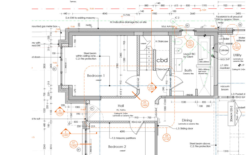
Dimensioning is best visualised on a plan – here is an extract from a Building Regulations drawing to help you. A Planning drawing will of course have a lot fewer dimensions.
A note about scale
Even though the drawing may be to scale, don’t use your ruler. Trust the dimensions written on the page – those are the correct ones. Printers lie. PDF’s sometimes lie. The numbers don’t.
If you want to print a drawing ‘to scale’ have a little look on the title bar section of the drawing sheet. Usually you will see something like Scale = 1:100 @ A3. Now you know that that drawing needs to be printed (not scaled in your printer settings) on an A3 sheet.
Reading architectural drawings is a bit like learning to read music – confusing at first, but much easier once you know what the lines and symbols are trying to say. I can’t read music…. so I hope for this to be the case!
If you’re ever stuck, please ask. We don’t expect you to be fluent.